Engr 415
Manipulator Design
Overall design

3D printed part

*timing belt, screws, bolts, nuts, washers were not included in the model
Built model
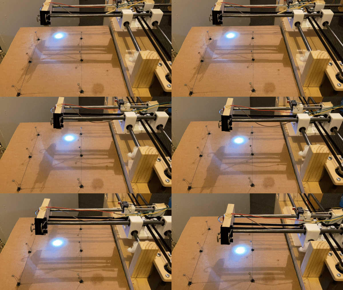
For the overall design of the manipulator, we went with an xy plotter design that can be found on the internet. It's mechanism is similar to the CoreXY system some 3D printers use and we will go over that later. As for materials, you can see in the figure to the right we used cardboard, wood, and a 3D printed part.
The functionalities of the manipulator was to:
1) be able to send directions to the master operator
- done with the joystick
2) move the beam within the play area
- done with the LED, stepper motors, and limit switches
3) send which shipping port to destroy
- done with with the photoresistors
4) indicate to the standby operator how many ports are destroyed
- done with 7 segment display

Manipulator Mechanism
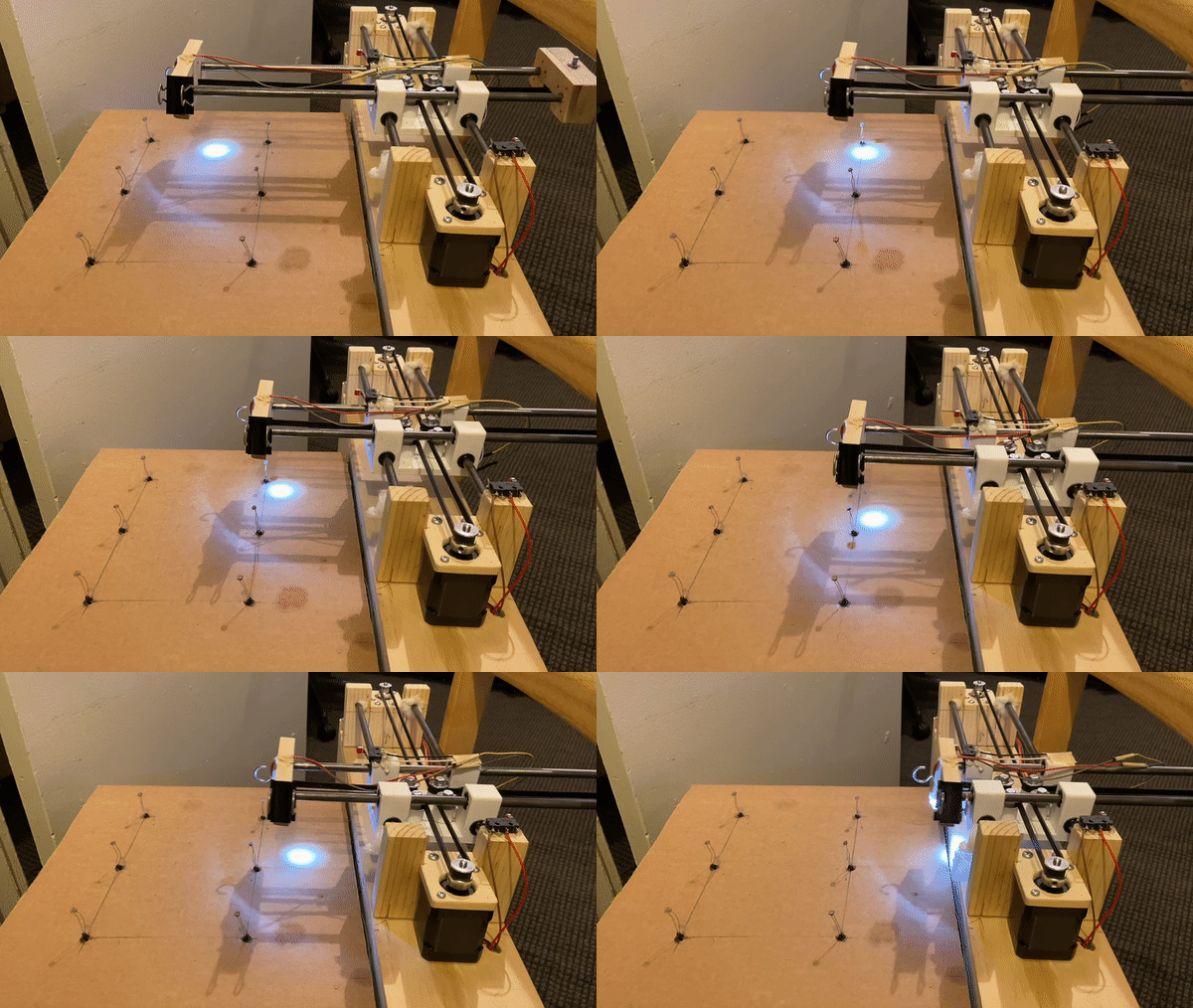
As mentioned above, the CoreXY system is used to move the LED around the play area. The idea of CoreXY is that both motors control some x and some y depending on which way you rotate the motor. If we look at the first 2 rows in the table to the right, when motor A rotates some angle theta CCW, then a reference position will move x/2 and -y/2. When motor B rotates some angle theta CCW, then the position will move x/2 and y/2. When combining these movements as shown starting at the 5th row, a clean vertical and horizontal movement can be done with the help of a microcontroller.

One motor moving at a time


Alternating motor movement
