top of page
Engr 415
Initial Design
-
This circuit schematic was made before knowing how to code the Sensor
-
The control box was initially thought to be made with a 3D printer.


Final Design


Key Differences

-
The final design is a couple millimeters bigger than the first design so the fan wouldn't hit any other sensors
-
MPU-6050 orientation changed to use X-axis of the gyroscopic sensor.
-
Final design includes an ESP32 microcontroller to allow WIFI capabilities.
-
MPU-6050 needs to be on pins 20 and 21 in order for I2C communication.
-
Motor controller changed from a N-Channel Mosfet to L293D and some diodes to allow for bidirectional control.
-
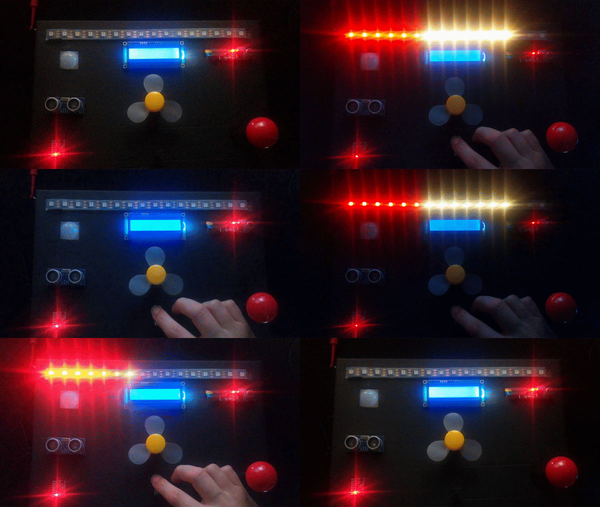
The Control panel made from foam core
-
LED strip has 16 visible LEDS
-
Tilt switch not visible on breadboard not front Panel
Sensors
bottom of page


